
Lighting Is the Real Specification
Experienced vision engineers will tell you that illumination matters more than camera resolution. A defect invisible under poor lighting cannot be recovered by a better sensor, while correct lighting makes a modest camera perform impressively. Choosing the right technique is the highest-leverage decision in an inspection station.
Backlighting: Silhouettes and Dimensions
A backlight places the source behind the part so the camera sees a silhouette. This produces extremely high contrast at the part edge, making it ideal for dimensional measurement, hole verification, presence detection and detecting missing material. Transparent or translucent parts can be inspected for internal inclusions with the same technique.
Ring Lighting: General Purpose Illumination
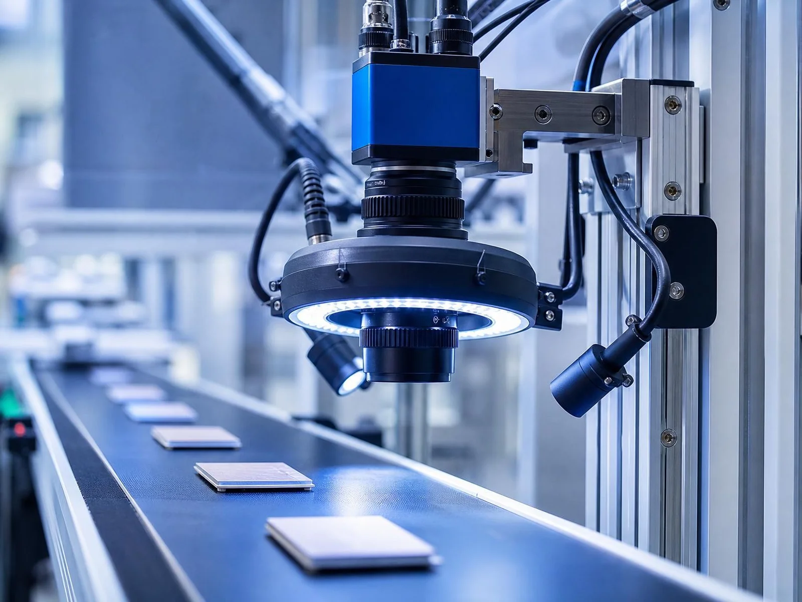
A ring light surrounds the lens and shines directly onto the part. It is the most common choice because it is flexible and inexpensive, providing even illumination for presence, position and basic surface inspection. Low-angle rings emphasise surface texture and can reveal scratches and dents that direct lighting washes out.
Dome Lighting: Diffuse and Forgiving
A dome light encloses the part in a hemisphere of diffuse illumination, eliminating shadows and reflections. It is the technique of choice for curved, shiny or machined surfaces where specular highlights would otherwise create false readings. Dome lighting is particularly effective on metal stampings, threads and castings.
Coaxial Lighting: Mirror-Like Surfaces
Coaxial illumination directs light along the same axis as the lens, using a beamsplitter. Flat, reflective surfaces return the light directly to the camera and appear bright, while angled or scratched areas scatter it and appear dark. This makes coaxial lighting highly effective for inspecting polished, flat surfaces, wafer and glass defects, and engraved or laser-marked features.
Dark-Field Lighting: Surface and Edge Defects
Dark-field illumination strikes the surface at a very shallow angle. A smooth surface reflects the light away from the camera and appears dark; scratches, pits, burrs and edge defects scatter light into the lens and appear bright. It is the standard approach for detecting surface imperfections on machined or polished parts.
Structured Light and 3D Measurement
Projecting a known light pattern allows a system to compute three-dimensional shape. This supports height measurement, coplanarity checks, solder joint inspection and volume estimation — capabilities beyond what two-dimensional imaging can provide.
Practical Selection and Stability
Start from the defect: edge measurement favours backlight, shiny curved surfaces favour dome, flat reflective parts favour coaxial, and surface flaws favour dark field. Whatever the technique, stability matters as much as principle. Intensity must be constant over time and unaffected by ambient light, which usually means enclosed stations, strobed sources synchronised to the trigger, and a controlled or sealed environment. Lighting chosen for the sample on the bench and left unstabilised on the line is a common cause of intermittent false rejects.