What Sheet Metal Fabrication Covers
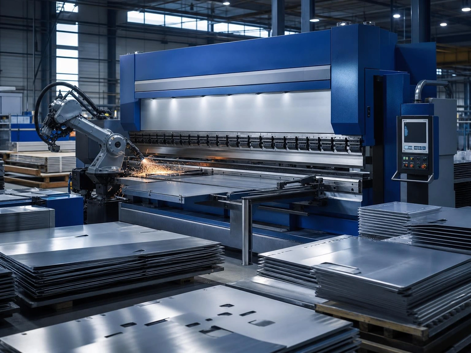
Sheet metal fabrication turns flat stock into functional parts and structures through a sequence of cutting, forming, joining and finishing operations. It is the backbone of enclosures, brackets, frames, panels, chassis and machine guards — parts that are strong, light and economical in volume.
The Core Processes
- Cutting — fibre laser cutting handles complex profiles with a small heat-affected zone; punching suits high volumes of repetitive shapes; plasma and waterjet cover thicker or heat-sensitive material.
- Bending — press brakes form flanges and channels. Tooling radius, material thickness and bend allowance determine what is achievable.
- Joining — spot welding, MIG or TIG welding, riveting and clinching each suit different materials and load requirements.
- Finishing — deburring, powder coating, painting, anodising, plating and silk screening protect the part and give it a finished appearance.
Understanding Realistic Tolerances
Sheet metal is not machined stock, and tolerances follow the process. Cut profiles typically hold tighter than formed dimensions, because bending introduces springback that varies with material grade, thickness and grain direction. Cumulative tolerances also grow across multiple bends, since each operation adds its own variation. Specifying generous tolerances where the function allows keeps cost down; over-tightening them on a formed part usually adds inspection and rework rather than quality.
What to Include in a Quote Request
A complete enquiry shortens the path to an accurate price:
- 2D drawings or 3D models with material grade and thickness
- Quantities, including whether the figure is a one-off or an annual volume
- Surface finish and colour requirements
- Any hardware, inserts, threads or fasteners to be fitted
- Acceptance criteria and any certification needed
Design Choices That Reduce Cost
Standard material thicknesses cost less than special orders. Bend radii matched to standard tooling avoid custom setup. Holes positioned away from bend lines prevent distortion, and a consistent bend direction reduces handling between operations. Where a part combines several small assemblies, reviewing whether it can be consolidated into fewer formed pieces often reduces both cost and assembly time.
Prototype to Production
Prototyping validates fit and function before tooling investment. A capable fabricator should support the full path — a small batch for testing, then process refinement and repeatable production with documented inspection, so the part arriving in volume matches the part that passed the prototype.